IDL> pts=fltarr(3,1000)
IDL> t=findgen(1000)/1000*3.14159*2*30
IDL> pts(0,*)=10*cos(t/3)
IDL> pts(1,*)=10*sin(t/5)
IDL> pts(2,*)=10*sin(t/2)
IDL> mkpov,pts,'img01.pov'
IDL> $x-povray +Iimg01.pov +D 2>err
|
We're going to examine the file
img01.pov
which makes the picture at right. The file was generated with
the following commands, which are described in more detail
on the main page.
IDL> pts=fltarr(3,1000)
|
|
Let's look at this file:
#include "colors.inc"
#include "shapes.inc"
#include "textures.inc"
camera {
   location <      11.0000      11.0000      64.0000>
   look_at  <      11.0000      11.0000      30.0000> }
light_source { <13,12,65> color White}
You can place light sources of any color in any position. These
are like lamps shining equally in all directions.
background {color rgb <1,1,1>}
Pixels that aren't otherwise assigned a color get this
color: <1,1,1> is equal to white. Note that I could have
said also "color White" like I did for the light source. You can
specify colors either with words (from the colors.inc include
file) or with red/green/blue values.
#declare R1 =      0.500000
#declare R2 =       1.00000
These two numbers set the radius of the spheres, and the radius of the cylinders, respectively. (The cylinders are used to draw the box around the data.) You may want to change these values. R1 is set by the keyword 'radius' to mkpov. But, you can change them after the fact by editing this pov file, that's why it's handy to have them set at the top of this file by the #declare statements.
#declare ballfin = finish {
   reflection 0.0 diffuse 0.4 ambient 0.7 phong 1.0 phong_size 300}
This describes the surface of the spheres. Try playing
with these numbers to see what they do. The numbers should
be between 0 and 1 (except for phong_size).
#declare redcolor = texture {
   pigment {color rgb <1,0,0>}
   finish { ballfin }}
Sets the default color of all the spheres. You can vary the
red, green, blue values.
#declare boxtex = texture {
   pigment {color rgb <0.6,0.8,1>}
   finish { reflection 0.0
      diffuse 0.4 ambient 0.7 phong 0.0 }}
Controls the appearance of the box. The color is light blue.
sphere { <      21.0000      11.0000      30.0000>, R1
   texture { redcolor }}
sphere { <      20.9803      11.3769      30.9411>, R1
   texture { redcolor }}
sphere { <      20.9211      11.7533      31.8738>, R1
   texture { redcolor }}
 .
 .
 .
Here we just start listing the spheres. The format is to list
the XYZ positions, then the radius (which is the previously
defined value R1 in this case), then describe the surface of the
ball (which is "redcolor" as previously defined). You can
replace R1 with a number to control the size, and replace
redcolor with the complete definition to control the color and
appearance.
cylinder {
<      1.00000,      1.00000,      20.0000>,
<      21.0000,      1.00000,      20.0000>,
R2
open
   texture { boxtex }}
 .
 .
 .
Here's where we draw the cylinders that form the light-blue
box surrounding the data. For a cylinder, you specify the two
endpoints, and a radius.
sphere { <      20.9803      11.3769      30.9411>, R1
  texture {
    pigment {color rgb <      1.00000
,
      0.00000
,
   0.00392157
>}
    finish { ballfin }}}
First off, notice that it's OK to have extra spaces and returns
in the file. So really if this wasn't computer generated it
might look prettier to be like this:
sphere { <20.9803 11.3769 30.9411>, R1
  texture {
    pigment {color rgb <1.0, 0.0, 0.004>}
    finish { ballfin }}}
Here we've specified the red/green/blue values explicitly for
this sphere, thus giving it it's own color.
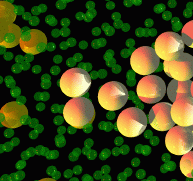
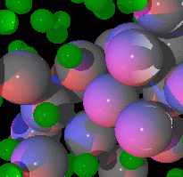
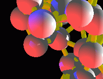
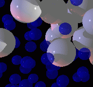
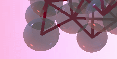
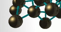
This has just barely scratched the surface of what POV-Ray can do, so if you want fancier stuff, you should look at the official POV-Ray home page. I've tinkered with POV files to generate the various effects you see below, which include balls with different textures, transparent balls, multiple colored light sources, connecting nearest neighbor spheres, and different colors.